minhbridge

WELCOME
Link to the engineering report
Spring Presentation Video
Winter Presentation Video
Fall Presentation Video
Figure 1A: Lift Device
Intro
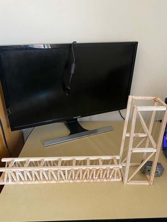
This Balsa wood bridge is a senior project designed by a CWU student. The bridge is entirely composed of Balsa wood and wood glue, with no other materials used. The Balsa wood bridge also has a lift mechanism to allow tall objects to pass under it. This bridge has a loading capacity of 20kg.

Minh's
Senior Project
BRIDGE

Analysis
Analyses of several bridge components have been done and are given below. The resulting calculations were utilized to generate a design that fulfills all specifications while being the most cost-effective and efficient. These studies were used to determine several design characteristics such as FBD, the cross-sectional area of components, maximum shear, and bending stress, and internal stress on each beam.

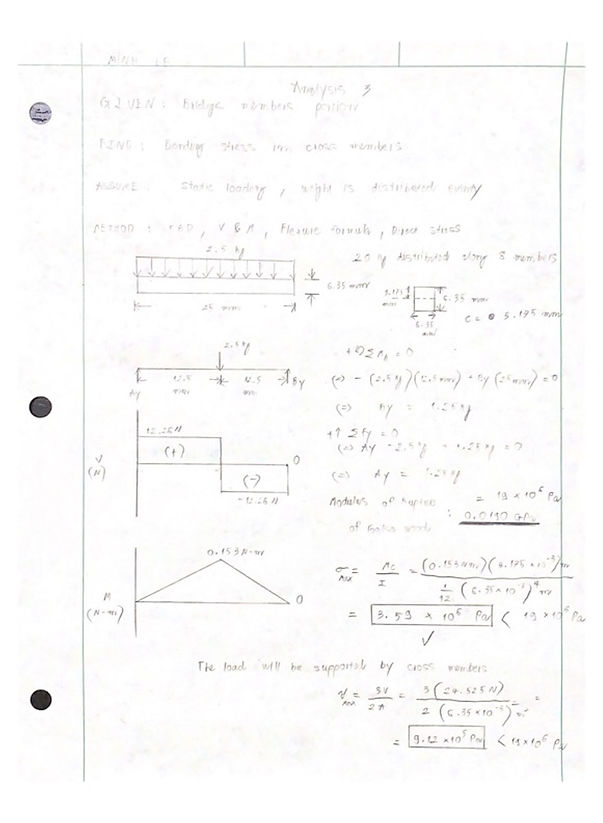
This analysis shows how a bending study was conducted to determine if the cross members could withstand a distributed load of 20 kg at the bridge's center. A distributed load's maximum shear stress is calculated and displayed in a shear and bending moment diagram. The maximum bending stress and shear stress must both be less than the modulus of rupture of balsa wood for this analysis to be valid. From this analysis, it is confirmed that the cross members of the bridge can support the 20kg weight without any rupture.

The lift mechanism was studied to prove the lift system was capable of lifting the bridge to the required height and sustaining it for an extended period, indicating that it met the specifications. Additionally, the lift tower demonstrated a high level of sturdiness and was capable of effortlessly supporting the weight of the bridge, indicating that it could remain elevated for even more extended periods.
The minimum needed length for the truss member was calculated in this analysis to meet two requirements: not overstressing the beam and staying within the prescribed weight of 85 grams. Using the maximum yield stress of balsa wood (woodsolutions.com) as the test point to compare the result. The minimum required base and width when using a squared gusset plate was determined to be 6.35mm. This analysis helps confirm the optimal cross-sectional area to not overstress the beams.

In this analysis, the objective is to determine the number of top cross members required to support the load. The condition for this analysis is that the number of cross members must be an even number in order to evenly distribute the load between the two sides of the bridge. The analysis involves studying the diagram and calculating the weight. To provide optimal support, the distance between every two top cross members is set at 56mm. By considering all this information, it is concluded that there should be 8 top cross members, which meets the specified requirements for the load distribution.

The objective of this analysis is to determine the amount of gusset plates required to connect and strengthen beams. The primary requirement for this analysis is that the total weight of the gusset plates should not exceed 8 grams. This limitation is imposed to ensure that the overall weight of the bridge does not exceed 85 grams, and the gusset plates do not account for more than 10% of the total weight. The weight of each gusset plate is determined by creating a prototype with trial dimensions in SolidWorks. Whenever there are more than two beams connected to each other, a gusset plate is necessary to provide support and strengthen the structure. In this case, 27 gusset plates are needed on each side of the bridge.

This analysis focuses on determining the maximum stress that a gusset plate can withstand before breaking. Free Body Diagram (FBD) and the shear force formula, are utilized to solve this analysis. The free body diagram of the gusset plate reveals the presence of one right triangle and two rectangular shapes. This information aids in determining the contact area of the gusset plate, which is calculated to be 336 mm². To calculate the shear force, the assumed resultant force is first determined, which amounts to 0.83N. By applying the shear force formula, the final result is determined to be 2470 Pa (pascals), which surpasses the requirement of 1kPa. Consequently, the gusset plate is capable of withstanding a stress of 2470 Pa before failing.
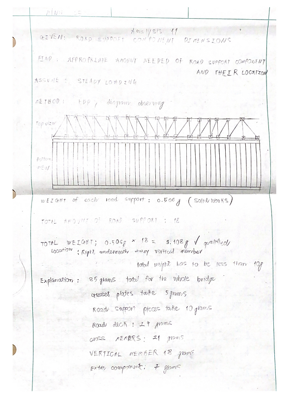
The objective is to determine the required number of road support members to effectively support a 20kg load. The analysis employs diagram observation and algebraic calculations as methods to determine the necessary number of road support members. Based on the trust assembly design of the bridge, it is determined that there should be a road support member positioned beneath each vertical member to provide stabilization. Therefore, a minimum of 18 road supports is required for the bridge design to be structurally sound. The analysis concludes that 18 road support members, with a total weight of 9.108 grams. This ensures the stability and functionality of the bridge's road support system.

The objective of this analysis is to determine the maximum stress that the bridge can withstand before failure. The methods employed to solve this analysis include the Free Body Diagram (FBD) and the tensile formula. According to the data obtained from Solidworks, the total contacted area between the road support members and the two horizontal bars amounts to 5987 mm². Considering the applied load of 20kg, the tensile formula is applied to calculate the resulting stress. The final result is determined to be 32800 Pa (Pascal), which is below the specified shear strength of 1.10 MPa( of Balsa wood). This analysis demonstrates that the road support members and the horizontal bars can adequately support the 20kg load, as they do not experience tensile stress greater than the shear strength of Balsa wood
Figure 1: SKETCH

Figure 1: Sketch

Figure 2: Sketch
Figure 3: Sketch
RESULTS
The bridge testing process yielded positive results, demonstrating that the bridge is functional and meets the specified design requirements. The test of the bridge's lift mechanism identified some initial issues related to the string connecting the lift tower and the bridge, as well as the surface on which the bridge was placed resulting in a successful test outcome. The second test evaluated the dimensions and capacity of the bridge's road deck, and the results indicated that the block could move smoothly across the entire length of the road deck with minor resistance and within the predicted time frame. In the load-bearing test, the bridge was able to support a load of 20kg without any signs of significant deformation or structural damage. The bridge remained stable throughout the test period, and there were no signs of any structural failure. These results indicate that the bridge is capable of meeting the required safety standards and can support the expected weight and traffic load
The bridge lift mechanism is tested to ensure that it remains elevated for 10 seconds without external help. The first stage is to identify what specifications the bridge must satisfy in order to pass the test. This includes the ten seconds that the bridge must stay elevated. The test must also contain data collection monitoring device, such as a timer and Excel data sheet. This data is crucial in analyzing the bridge's performance throughout the test and serves as the foundation for making any required improvements to improve its performance. The test should be repeated several times to guarantee consistency and to offer a more accurate assessment of the bridge's performance. Properly setting the bridge on a level surface and securing it in place to avoid movement during the test. Some difficulties did arise, however, throughout the testing process, which were resolved by taking measures. It was able to improve the accuracy of the testing results and verify that the bridge fulfilled the required criteria by solving these issues.

In order to complete this project, a set of deliverables were required that covered a range of data sheets documenting all the testing and measuring of the bridge requirements. The results obtained from the testing process include numerical values that detail the measurements of the bridge and the amount of load it was able to hold before failing. Along with the numerical values, pass/fail results from the requirements will also need to be included in the data sheets
Construction

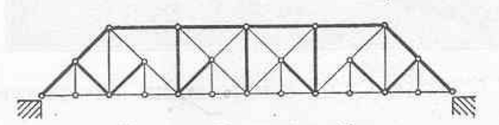
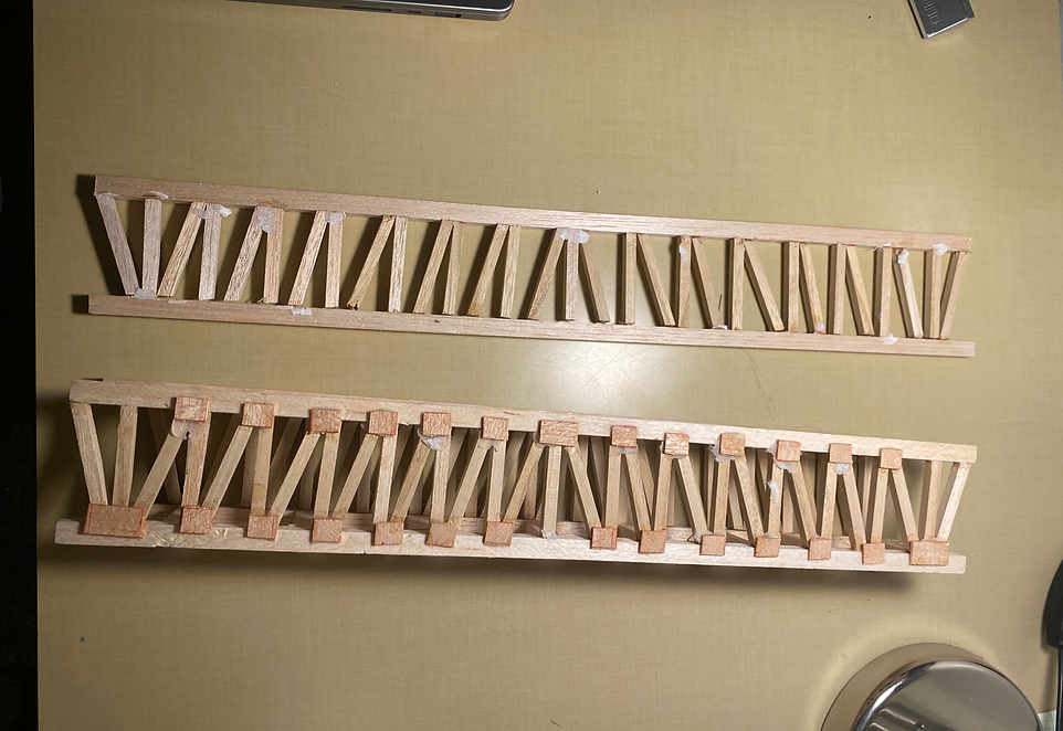
These are the vertical bars (MLV-20-012) for the two side trusses. There are 16 bars on each side. Making a total of 32 bars for the entire bridge. The bars have dimensions of 6.35 x 50 x 6.35. Construction was completed using a precision cutter knife, ruler, and sandpaper. An extra 3mm was added to each piece. This allows the next finishing cut to be cleaner and sanded without affecting the required length of the bars. After cutting each piece required light sanding to correct any small defects caused by blade deflection. Final step is to take measurements and make sure all the parts are within tolerance (any part that deviated no more than 0.5mm was considered acceptable)

The road support bars (MLV-20-008) to connect the two side trusses are seen here. There are a total of 18 bars under the road deck. The measurements of the bars are 6.35 x 32 x 6.35. A precise cutting knife, ruler, and sandpaper were used to complete the construction. Each component was given an additional 2mm. This enables for a cleaner and sanded next finishing cut without impacting the needed length of the bars. Each piece needs minimal sanding after cutting to rectify any minor flaws caused by blade deflection. The last step is to take measurements and ensure that all of the pieces are within tolerance (any part that deviated no more than 0.5mm was considered acceptable)
.jpeg)
These cross bars, designated as MLV-20-011, are an essential component of the two side trusses. There are a total of 32 cross bars required to construct these two trusses along with 30 vertical bars (MLV-20-12). To speed up the production process and ensure accuracy, an angular miter shear has been obtained to cut the bars to a precise 75-degree angle, eliminating the need for re-measuring after every cut. Additionally, each bar has had an extra 2mm added to its length to protect the required measurement during the sanding process and provide a better overall finish. The final step in the process is to take measurements to ensure that all pieces are within tolerance, with any part deviating no more than 0.5mm considered acceptable.

The 2 lifting towers on the 2 sides of the bridge are comprised of 8 vertical components(MVL-20-003). These components have dimensions of 6.35 x 250 x 6.35 mm and were carefully crafted using a precision cutting knife, ruler, and sandpaper. To ensure a smooth and polished final cut, an additional 2mm was added to each component during the construction process. Minimal sanding was required to correct any minor imperfections caused by blade deflection during the cutting process. Finally, thorough measurements were taken to ensure that each component was within tolerance, with deviations not exceeding 0.5mm deemed acceptable.

The 2 lifting towers consist of horizontal components, with a total of 9 bars on each side of the tower (MVL-20-003). The bars are dimensioned at 6.35 x 38 x 6.35 mm and were constructed using a sharp cutting knife, a ruler, and sandpaper. To achieve a smooth and polished final cut, an additional 2mm was added to each component, enabling minimal sanding to correct any slight imperfections caused by blade deflection. Finally, all pieces were meticulously measured to ensure they meet the necessary tolerance standards. Any component that deviated no more than 0.5mm was considered to be within acceptable limits.

Angular miter shear to produce angle cuts on components of the bridge. Not all cuts are reliable due to the heavy blades which damage the wood sometimes.

Damaged component caused by the angular miter shear. Therefore to counter the problem, components were cut first halfway using angular miter shear and the second half using a precision cutter knife.
Construction Methods
The balsa wood bridge project involved creating components using square stock material, which were cut to the proper angle and length using precision cutter knives and miter shears. A 73-degree cut was required to form cross members on the two side trusses and was achieved easily with the help of angular miter shears. A 90-degree cut was easily made using a precision cutter knife. A drawing of one of the two trusses was sketched on A-2 paper and used as a background to ensure precision and accuracy in the assembly. An issue was encountered with vibrations from the free hanging ends while cutting, but it was resolved by adjusting the material bar and using a heavy book to firmly press the other end down. Many rejects were produced during the 73-degree cut due to the heavy weight of the blade and the large amount of force applied to the miter shears. A solution is to reduce the force applied to the miter shears and only use them halfway through the material. The second half will be cut using a precision cutter knife. A little sanding is required for every bar after each cut to provide a better finish.

TESTING
The balsa wood bridge was tested on several criteria for the project. A 32mm x 25mm block (acting as a vehicle) must be able to traverse the bridge on the road deck uninterruptedly, the bridge's articulation system must be able to raise the bridge for at least 10 seconds without external assistance and the bridge must be able to support a load between 18.9kg and 20 kg (without the articulation system).
For the first test, the bridge must be lifted for 10 seconds per the requirements. The bridge initially stayed up for 15 seconds before failing, raising questions about the bridge's functionality. However, following a thorough investigation, it was determined that the string connecting the lift tower and the bridge was already worn out and of poor quality, and this problem was resolved by replacing the string with a higher-grade string. The bridge stayed raised for more than a minute after the string was replaced. The bridge lift mechanism testing procedure was successful in validating the bridge's performance in accordance with the specifications
The second test was performed to evaluate the dimensions and capacity of the road deck by pushing a 32 x 25mm block across the whole length of the road deck. Several difficulties emerged during the testing method. The first challenge was the unevenness of the road deck's surface, which made it impossible to push the block consistently. To achieve a smooth surface, all protruding edges were sanded down and any gaps were filled up by replacing a better-quality road deck. The second difficulty was that the block was initially extremely heavy, producing considerable friction and making movement difficult. To address this issue, the testing method was carried out on a lighter block
1st Test
The bridge remained lifted for 10s
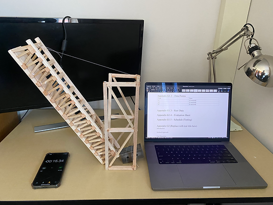
The bridge is capable of articulating to the designed height and remaining raised at that height for 15 seconds without any external force. The predicted value was that the bridge would remain raised using only its own lifting mechanism for 10 seconds as per requirement since the lift tower and the articulating system were extremely stable and reliable. A stopwatch and data collection sheet were used to record the time for which the bridge remained in the raised position

The bridge at rest with lifting tower. Extra precautions should be taken to minimize physical damage to the structure while securing it in the right testing position. Even though the bridge could be raised for hours but it's not recommended to leave the bridge in lifted position for a long period of time as this could potentialy damage the lifting tower. Rest position should be applied.
Testing Method
The bridge lift mechanism is tested to ensure that it remains elevated for 10 seconds without external help. The first stage is to identify what specifications the bridge must satisfy in order to pass the test. This includes the ten seconds that the bridge must stay elevated. The test must also contain data collection monitoring device, such as a timer and Excel data sheet. This data is crucial in analyzing the bridge's performance throughout the test and serves as the foundation for making any required improvements to improve its performance. The test should be repeated several times to guarantee consistency and to offer a more accurate assessment of the bridge's performance. Properly setting the bridge on a level surface and securing it in place to avoid movement during the test. Some difficulties did arise, however, throughout the testing process, which were resolved by taking measures. It was able to improve the accuracy of the testing results and verify that the bridge fulfilled the required criteria by solving these issues.
2nd Test
The object (vehicle) traverses the road deck

Preparations for the second test are underway, and the required items have been gathered. These include a timer, the bridge, and an object that represents the vehicle

The vehicle representation was pulled along the entire length of the road deck using a string. The block traveled smoothly without any obstructions and completed the entire road deck in just 20 seconds. A photograph was captured at the 9-second mark when the block had already traveled half the length of the road deck

During the second test, a significant challenge arose when it was discovered that the original road deck of the bridge was not sturdy enough to bear the weight of the block. Unfortunately, the block caused damage to the road deck after the initial trial. A photograph was taken, which clearly shows the crack in the road deck caused by the weight of the block

This picture shows the newly replaced road deck, which has been constructed using a higher quality piece of Balsa wood compared to the original one. Several trials were conducted on the new road deck, and it displayed remarkable sturdiness, with no signs of damage whatsoever

Testing Method
For the second test of the bridge's road deck, which involved the use of a 32 mm wide by 25 mm high block to simulate a vehicle crossing. The method involved specifying the exact requirements for the test, such as the size of the block and the block's successful completion of the test. Safety measures were taken, including the construction of a non-slip surface, high quality road deck and the use of a lightweight block. Data was collected using tool such as a timer to monitor performance and identify issues. Modifications to the testing procedure were made to overcome challenges related to the weight and slipperiness of the block, ensuring that the bridge met design requirements while maintaining safety.
3rd Test
Load Bearing Test

This picture shows the setup for the load-bearing test, where the container bag is suspended from the midpoint of the road deck. The bag is constructed from durable nylon material, capable of withstanding substantial loads. A cotton pad is positioned beneath the bag to prevent any damage to the floor.

This picture shows the bridge is supported by 60 mm wide abutments, without any mid-span supports.
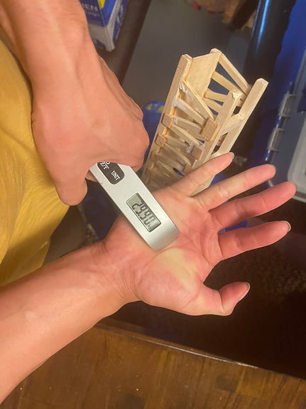
This picture captures the handheld scale in action, weighing the bag. It reveals a weight of 29.9kg, while the bridge impressively handles this load with only slight signs of deformation and cracking.
Testing Video
Testing Method
The third test aims to evaluate the bridge's strength and durability as it supports a minimum weight of 20 kg. The testing location was carefully chosen to ensure a level surface and accurate weight measurement. To assess the bridge's weight-bearing capacity, a bag containing heavy objects was incrementally placed on the bridge, and the weight was recorded using a handheld scale. The bridge was then left in place for a set period to determine its ability to withstand the weight. After the weight was removed, the bag was weighed again to obtain an accurate measurement (29.9kg). The bridge was thoroughly inspected for any signs of damage or deformation, and any observed defects were meticulously recorded. Overall, this testing technique provided reliable and accurate results, indicating that the bridge was strong enough to support a minimum weight of 20 kg and durable enough for future use.
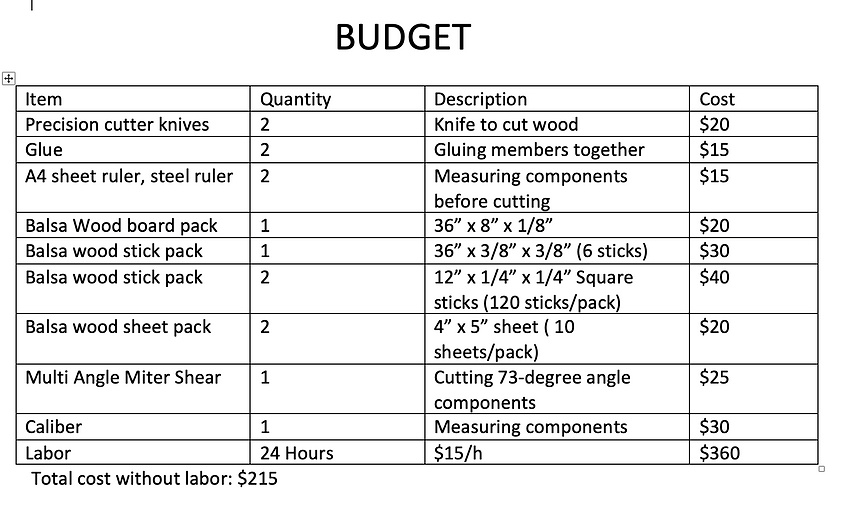
Budget
Due to the fact that the entire bridge structure will be constructed out of balsa wood and glue this project will primarily be made of materials that are readily available after purchases. This makes it simple to obtain the materials listed in Appendix C's section on parts and budget. The majority of the time, Amazon has been used to order the precise sizes of balsa wood pieces, along with other tools needed, like a knife, a saw, and the glue that will be used to build the bridge as shown in Appendix D. It would be best to order components with the extra quantities in case multiple tests could occur due to failure and also because prices and materials can change quickly between the time of planning and the actual testing. There won't be any outsourcing of the bridge's manufacturing. The balsa wood was responsible for the majority of this expense.
During the winter quarter, the project faced a number of difficulties with the components that were ordered. To begin with, there was a setback with the delivery of the components as they arrived a week later than expected due to a missing package incident. Despite this setback, the project team had taken the necessary steps to order the components well in advance, which helped to minimize the impact on the overall project timeline. However, the budget for the project took a significant hit as a result of the delay. The team had to quickly reorder the components in order to ensure that they arrived on time, while the supplier assessed the claim case for the missing package. This rush to reorder the components caused the project budget to nearly double, which was a severe blow to the project's financial planning. Despite this setback, the majority of the components have now been successfully manufactured, and the project is moving forward as planned.
Budget/Schedule
For fall quarter, coming up with the design and analysis for the bridge are the key points. In order to achieve the desired model of the bridge, a lot of sketches and FBDs were constructed to help visualize the final product. After 2 weeks of deciding on the final design of the bridge, the lift mechanism of the bridge is the next part need to be considered. According to the requirement, the lift mechanism can be either manual or automatic. To achieve the main goal of the project, which is to be cost-effectiveness and efficiency, the lift mechanism will be operated manually. The designs for both the bridge and the lift mechanism have been decided, next part is to analyze and calculate other factors of the bridge like truss members’ dimensions, cross members’ dimensions, lift system, etc. All 12 analyses about the bridge will be done in the fall quarter. Ordering and manufacturing parts for the bridge will also be accomplished so that for the winter quarter the project can have a faster pace in case unwanted delays interfere. The budget and list of parts will also be listed in the final paper. Moreover, all drawings of parts and assemblies of the bridge and the lift system will be finished at the end of fall quarter.
The Balsa Wood Bridge project began construction in winter 2023 and ended at the end of the quarter. The construction phase was detailed in Appendix E with its activities and timeline. The project faced challenges with the delayed delivery of the sole material, Balsa wood, and issues with its quality and size upon arrival. A method for constructing the bridge was implemented while waiting for the material, and practicing was done on disqualified materials to gain experience. The ordering process was done ahead of schedule and there have been no further issues with the project's completion timetable. The production phase was completed in 15 hours, saving 9 hours compared to the planned time.
Gantt chart
